 English
 русский
 Français
 Español
 Português
 Deutsch
 عربى
عربى Türk
Türk
Heavy Duty Cable Roller Selection, Installation, and Maintenance Guide
Content
- 1 What Separates a Heavy Duty Cable Roller from a Standard Roller
- 2 Core Types of Heavy Duty Cable Rollers and How They Work
- 3 Application Scenarios Where Heavy Duty Cable Rollers Matter
- 4 Selection Criteria for Heavy Duty Cable Rollers
- 5 Heavy Duty Cable Roller Specifications Compared
- 6 Installation and Maintenance Practices for Long Service Life
- 7 Sourcing Heavy Duty Cable Rollers from a Manufacturer
- 8 Frequently Asked Questions about Heavy Duty Cable Rollers
- 8.1 What is the working load limit of a heavy duty cable roller?
- 8.2 How do I choose between a V-groove and a U-groove roller?
- 8.3 Can a heavy duty cable roller be used for wire rope?
- 8.4 How often should cable rollers be inspected?
- 8.5 What causes a heavy duty cable roller to fail early?
- 8.6 Are stainless steel rollers necessary for coastal projects?
- 8.7 Can I use a standard roller for a heavy pull if I add more rollers?
- 9 Related Resources from Our Workshop
When a 12-ton cable reel stalls halfway through a tunnel pull, the cost is rarely just the roller that failed. The crew stops, the winch cools down, the cable jacket may already be scarred, and the schedule slides by hours or days. In most of those incidents, the root cause traces back to a heavy duty cable roller that was underspecified for the actual line load, misaligned on the trench wall, or fitted with a bearing that was never sealed for the environment. A heavy duty cable roller is not a consumable accessory that can be chosen by eye. It is a load-bearing interface between the pulling equipment and the cable, and its geometry, metallurgy, and bearing system decide whether the pull stays smooth or turns into a repair job.
The practical conclusion first: for any cable pull above roughly 500 kg of line tension, or any route with curves, elevation changes, or abrasive ground, specify rollers by working load limit, bearing type, groove profile, and mounting method rather than by roller diameter alone. The rest of this guide explains why those four variables matter, how different roller designs behave in the field, and what buyers should verify before placing an order with a manufacturer or supplier. It also connects the same principles to wire rope handling, where heavy duty rollers often work alongside reeling, annealing, and swaging equipment.
What Separates a Heavy Duty Cable Roller from a Standard Roller
The difference is not simply a thicker side plate or a larger wheel. A true heavy duty cable roller is engineered around a higher working load limit, a more robust bearing system, and a groove geometry that keeps the cable centered under side loads. Standard rollers are frequently rated for 200 kg to 500 kg and use plain bushings or light ball bearings. Heavy duty versions commonly start at 1,000 kg and extend beyond 10,000 kg, with sealed bearings, forged or cast frames, and replaceable wear components.
Load rating is the first filter. A roller that is rated at 2,000 kg static may have a much lower dynamic capacity when the cable is moving, especially if the roller is mounted at an angle. Reputable manufacturers publish both static and dynamic working load limits, and they specify the maximum cable speed and ambient temperature. If a supplier only lists a single “capacity” number without defining whether it is static, dynamic, or breaking load, treat that number as marketing rather than engineering.
Bearing selection follows the duty cycle. Sealed deep-groove ball bearings suit high-speed cable pulls with moderate loads and clean conditions. Tapered roller bearings handle combined radial and axial loads, which appear when rollers are used on curves or when the cable pulls at an angle. Heavy-duty polymer or bronze bushings are still found in dirty, slow-speed applications because they tolerate shock and neglect, but they require more pulling force and generate more heat. In dusty tunnels or coastal environments, a sealed bearing with a labyrinth or lip seal prevents grit and salt water from reaching the rolling elements.
Material and coating choices determine corrosion life. Painted carbon steel is adequate for temporary above-ground pulls. Hot-dip galvanized steel, stainless steel, or nylon and polyurethane wheels are preferred for marine, mining, and chemical plants. The frame matters as much as the wheel: a stamped steel frame can flex under load and pinch the bearing, while a welded or forged frame keeps the roller aligned. Groove profile also deserves attention. A V-groove centers the cable but concentrates contact stress; a U-groove or flat-groove with radiused edges distributes load over a wider area and reduces jacket marking. For wire rope, a sheave-style groove matched to the rope diameter prevents flattening and bird-caging.
| Feature | Standard roller | Heavy duty cable roller |
|---|---|---|
| Typical working load limit | 200–500 kg | 1,000–20,000 kg |
| Bearing type | Plain bushing or light ball bearing | Sealed ball, tapered roller, or heavy bushing |
| Frame construction | Stamped or thin-walled steel | Welded, forged, or cast steel |
| Groove profile | Simple V or flat | Radiused U, sheave, or custom profile |
| Corrosion protection | Paint or light zinc | Galvanized, stainless, or polymer wheel |
| Typical service life | One or two projects | Multiple projects with maintenance |
A heavy duty cable roller is defined by its verified dynamic load limit, sealed bearing system, and groove geometry, not by its outside diameter or paint color.
Core Types of Heavy Duty Cable Rollers and How They Work
Roller type follows the route. A straight pull needs a different roller than a 90-degree corner, and a wire rope application may need a sheave rather than a trench roller. The working principle is consistent: replace sliding friction with rolling contact, keep the cable or rope centered, and distribute the side load into a frame that will not deform. When that principle is respected, pulling tension drops, jacket abrasion decreases, and the winch or capstan runs within its design envelope.
Straight Run Rollers
Straight run rollers are mounted in a line along the trench, duct bank, or floor. They are usually the simplest and most numerous type on a site. The key variables are roller spacing, height, and groove alignment. If rollers are spaced too far apart, the cable sags between them and creates a catenary that increases tension. If they are set too high or too low, the cable may lift off the groove or press against the frame. For heavy cable, a spacing of 2 to 3 meters on straight sections is common, but the final spacing should be calculated from cable weight per meter, allowable sag, and the roller’s working load limit.
Corner and Angle Rollers
Corner rollers are placed at bends, manholes, and direction changes. They experience combined radial and axial loads, so their bearing and frame must resist side thrust. A common mistake is to use a straight roller at a corner by simply turning the frame. That works only for very shallow angles. For 45-degree or 90-degree changes, a dedicated corner roller with a vertical axis or a multi-roller assembly keeps the cable in the groove and prevents it from jumping out under tension. Heavy duty corner rollers often include a guard or retaining pin, especially when the pull direction is not fixed.
Sheave Rollers for Wire Rope
Sheave rollers, sometimes called cable sheaves, are grooved wheels designed for wire rope and high-tension lines. They are used on cranes, lifting slings, tension stringing, and wire rope processing lines. The groove diameter must match the rope diameter closely enough to support the strands without crushing them. An undersized groove pinches the rope; an oversized groove lets the rope flatten and wear unevenly. Sheave rollers are frequently mounted in pairs or blocks to create a fairlead that controls the rope as it enters a winch, a reeling machine, or a swaging station.
Motorized Roller Guides
Motorized roller guides add powered rotation to assist long or heavy pulls. They are common in cable laying, pipe laying, and continuous wire rope processing. The motor can be electric, hydraulic, or pneumatic, and it is usually controlled by a variable-frequency drive or a proportional valve. Motorized guides reduce the line tension that the main winch must produce, but they also introduce new risks: speed mismatch between the guide and the winch can cause the cable to bunch or stretch, and a failed drive can turn the roller into a brake. For that reason, motorized roller guides should be specified with overload protection, emergency stop, and a manual release.
- Straight run rollers: line support, simple frame, high quantity.
- Corner rollers: direction change, side load resistance, retaining features.
- Sheave rollers: wire rope support, matched groove, high radial load.
- Motorized guides: long pulls, reduced winch tension, controlled speed.
Choose the roller type by the load direction and route geometry; a corner roller is not simply a straight roller turned sideways.
Application Scenarios Where Heavy Duty Cable Rollers Matter
Heavy duty cable rollers appear wherever a conductor, cable, or wire rope must be moved without damaging its outer layer or overloading the pulling equipment. The industries are broader than many buyers expect. Power transmission and distribution crews use them for underground cable installation. Telecom contractors use them for fiber optic pulls through ducts and manholes. Mining operations use them for trailing cables and shaft cables. Ports and shipyards use them for shore power and crane cables. Wire rope manufacturers and rigging shops use them to guide rope through reeling, annealing, and swaging lines.
In wire rope processing, the roller and the reeling machine work as a system. The reeling machine controls tension and spooling, while the roller guides the rope into the correct fleet angle. If the fleet angle is too steep, the rope rubs against the spool flange; if the roller is too far away, the rope may whip or jump the groove. A heavy duty roller with a sealed bearing and a matched groove keeps the rope aligned and reduces wear on both the rope and the spool. This is especially important when the rope will later be cut, annealed, or pressed into a terminal.
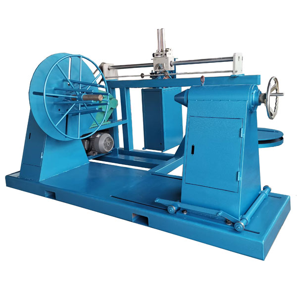 XT-1600 Wire Rope Reeling Machine for Controlled Winding and RewindingDesigned for winding and rewinding steel wire ropes, this machine offers stepless speed regulation, high torque, and accurate length measurement to support orderly spooling and reduce rope deformation.View Product →
For cable installation contractors, the roller is also a safety device. A roller that fails under load can release stored energy, whip the cable, or drop the reel. That is why many project specifications now require rollers with secondary retention, locking pins, and documented load tests. The same logic applies to temporary rollers used in manholes and trenches. Even if the roller is only needed for one pull, it must be rated for the worst-case tension, not the average tension. Shock loads from a winch start, a reel brake, or a sudden stop can exceed the steady-state pull by 50 percent or more.
Maintenance teams should also consider how the roller interacts with the cable jacket. A rough or damaged groove acts like a file. Over a long pull, it can remove the outer sheath and expose the metallic screen or armor. Once the jacket is breached, moisture ingress becomes a long-term reliability problem. For that reason, heavy duty rollers used on high-value cables should have replaceable polymer or bronze inserts, or at least a smooth machined groove that can be inspected and polished between projects.
Heavy duty cable rollers protect both the cable and the pulling equipment; they are a system component, not a temporary convenience.
Selection Criteria for Heavy Duty Cable Rollers
Selection starts with the cable. Record the outside diameter, weight per meter, minimum bend radius, jacket material, and maximum pulling tension. Then add the route conditions: straight length, number of bends, elevation change, ground surface, and exposure to water, chemicals, or extreme temperatures. With those inputs, the roller can be sized by working load limit, groove profile, bearing type, and mounting arrangement.
A simplified calculation helps. If a cable weighs 5 kg per meter and the unsupported span between rollers is 3 meters, the cable load on each roller is roughly 15 kg plus dynamic factors. That seems small, but the same cable under 2,000 kg of pulling tension can impose a much larger side load at a corner. At a 30-degree bend, the resultant force can be approximately equal to the pulling tension multiplied by 2 times the sine of half the angle. For 2,000 kg and 30 degrees, that is about 1,035 kg of side load. A 1,000 kg roller would be marginal; a 2,000 kg roller would provide a safer margin.
Groove profile should match the cable or rope. For power cable, a radiused U-groove with a width slightly larger than the cable diameter reduces point loading. For wire rope, a sheave groove with a radius of approximately 0.53 to 0.55 times the rope diameter is a common starting point, but the rope manufacturer’s recommendation should take priority. For flat cable or hose, a flat roller with raised edges may be preferable. In all cases, avoid a groove that is narrower than the cable, because it will pinch and deform the jacket or strands.
Bearing and sealing are the next decision. Clean, dry, high-speed pulls can use sealed ball bearings. Dirty, wet, or slow-speed pulls may benefit from tapered roller bearings or heavy-duty bushings. If the roller will be submerged or washed down, specify IP-rated seals or a maintenance-free polymer bearing. If the roller will operate in a food or pharmaceutical environment, stainless steel or food-grade polymer may be required. The mounting method also matters: bolt-on brackets, magnetic bases, clamp-on frames, and concrete anchors each have different load paths and installation tolerances.
To compare typical load demands across common applications, the chart below shows representative side-load ranges. These are planning values, not design limits; every project should be calculated from its own cable and route data.
The chart makes a consistent point: the required roller capacity rises quickly as the application moves from shallow underground work to offshore or shaft installations. Underground cable pulls often sit below 2 tonnes, while tunnel and mining projects regularly reach 3 to 5 tonnes. Port, shipyard, and offshore wind work can push side loads to 8 tonnes and beyond, especially when the route includes tight bends or vertical drops. The practical implication is that a single roller model rarely fits every project. Contractors who standardize on one heavy duty cable roller for all sites often end up either overspending on capacity they do not need or, worse, using a roller at the edge of its dynamic limit. A better approach is to define two or three capacity bands and stock rollers that cover each band with a clear safety margin.
Size the roller from the worst-case side load at bends and shock events, then add a margin; average pulling tension is not a safe design basis.
Heavy Duty Cable Roller Specifications Compared
When buyers compare catalogs, the specifications can look similar until the details are pulled apart. A 5-tonne roller from one manufacturer may have a 150 mm wheel, a 20 mm shaft, and a stamped frame, while another 5-tonne roller may have a 200 mm wheel, a 40 mm shaft, and a cast frame. Both may claim the same capacity, but their fatigue life, side-load stiffness, and repairability can differ significantly. The table below compares common specification bands rather than specific brands, so it can be used as a checklist during procurement.
| Specification band | Working load limit | Typical wheel material | Bearing type | Common applications |
|---|---|---|---|---|
| Light heavy-duty | 1,000–2,000 kg | Painted steel or nylon | Sealed ball bearing | Underground cable, telecom ducts |
| Medium heavy-duty | 2,000–5,000 kg | Galvanized steel or polyurethane | Tapered roller or heavy ball | Tunnel pulls, mining cables |
| High heavy-duty | 5,000–10,000 kg | Forged steel or stainless | Tapered roller, sealed | Port, shipyard, heavy rigging |
| Severe duty | 10,000–20,000 kg | Stainless or alloy steel | Large tapered roller or bushing | Offshore wind, shaft sinking |
The table shows that capacity bands correlate with material and bearing choices, but not perfectly. A 5,000 kg roller with a sealed ball bearing may be adequate for a clean, high-speed pull, while a 2,000 kg roller with a tapered roller bearing may survive a dirty, slow-speed corner better. That is why the application column matters. Buyers should ask the manufacturer to confirm the dynamic load rating, the maximum cable speed, the operating temperature range, and the expected service life at the intended duty cycle. A roller that is rated for 10,000 kg static may be limited to 3,000 kg dynamic, and the dynamic rating is the one that matters during a pull.
Another specification that is often overlooked is the shaft and mounting interface. A roller with a 20 mm shaft may fit a standard bracket, but it can bend under side load if the bracket is not supported on both sides. A 40 mm shaft adds stiffness and bearing life, but it also requires a larger frame and more space. In tight manholes, the larger frame may not fit. The solution is not always to choose the biggest roller; it is to match the roller to the available mounting envelope and to use a properly designed bracket that transfers load into the structure, not into the roller shaft alone.
Compare dynamic load ratings, bearing seals, and mounting stiffness together; a high static rating without a matching frame and bearing is not a heavy duty solution.
Installation and Maintenance Practices for Long Service Life
Correct installation prevents most roller failures. The first rule is alignment. The roller groove should be parallel to the cable path and at the same height as the cable entry and exit points. If the roller is mounted at an angle, the cable will ride against one side of the groove, creating a side load that the bearing was not designed to carry. The second rule is support. The bracket or frame must be anchored to a rigid structure, not to loose soil or a temporary timber. If the roller is mounted on a trench wall, the wall should be stable and the bracket should be bolted, not wedged. The third rule is spacing. Rollers that are too far apart allow the cable to sag and rub; rollers that are too close waste time and create unnecessary joints.
During the pull, inspect the rollers at each stop. Look for cable jacket dust, which indicates abrasion. Feel the roller for excessive heat, which indicates bearing friction or misalignment. Listen for squealing or grinding, which can signal a failing bearing or a dry bushing. If a roller is hot or noisy, stop the pull and correct the issue before continuing. Continuing a pull with a bad roller can damage the cable, the roller, and the winch. After the pull, clean the rollers, remove debris from the grooves, and check the bearings for play. If the roller has a grease fitting, add the recommended grease until clean grease appears. If it is sealed, do not attempt to open it; replace it if it feels rough.
For wire rope and cable processing lines, maintenance should follow the same discipline as other hydraulic and mechanical equipment. Rollers that guide rope into a reeling machine should be checked for groove wear and alignment every shift. A worn groove can flatten the rope and create a weak point. Rollers that guide rope into a swaging or annealing station should be inspected for heat damage, especially if the rope is hot. In those environments, a high-temperature bearing or a bushing may be needed. The same maintenance principles that apply to wire rope hydraulic presses and reeling machines apply to rollers: keep them clean, aligned, and within their load rating.
Related maintenance guidance can be found in our notes on maintenance precautions for wire rope hydraulic presses and wire rope rolling machine applications. These articles explain how lubrication, alignment, and load control affect the life of the entire processing line, not just the roller.
Alignment, rigid mounting, and regular groove inspection prevent the majority of heavy duty cable roller failures.
Sourcing Heavy Duty Cable Rollers from a Manufacturer
Buying a heavy duty cable roller is not the same as buying a commodity hardware item. The supplier must be able to confirm the dynamic load rating, provide material certificates, and explain the bearing seals. If the roller is intended for a specific project, the manufacturer should be willing to review the cable diameter, route geometry, and pulling tension. A supplier who cannot answer basic engineering questions is a risk, even if the price is low.
Start by requesting a dimensional drawing with tolerances for the groove, shaft, and mounting holes. Ask for the bearing part number and manufacturer. Ask whether the frame is welded, forged, or cast, and whether it has been stress-relieved. Ask for a test report for the load rating, not just a catalog page. If the roller will be used in a corrosive environment, ask for the coating thickness, salt-spray test results, or the stainless steel grade. If the roller will be used with wire rope, ask for the recommended groove radius and the rope diameter range.
For volume buyers, a factory relationship offers advantages. A manufacturer can produce custom groove profiles, mounting brackets, and colors to match a fleet. They can also provide spare wheels, bearings, and shafts so that rollers can be rebuilt rather than replaced. A wholesaler or distributor may carry stock, but they may not have the engineering depth to support a complex pull. The best approach is often to buy standard heavy duty rollers from a manufacturer for routine work and to engage the same manufacturer for custom rollers on critical projects. That keeps the supply chain simple and ensures that spare parts are available.
Delivery and documentation should be part of the purchase order. Specify that each roller arrives with a load test certificate, a material certificate, and a maintenance sheet. Specify the packaging so that grooves and bearings are protected during transport. If the rollers will be stored outdoors, require corrosion protection that will survive at least six months. Finally, confirm the warranty terms and the spare parts lead time. A heavy duty cable roller is an investment; the total cost of ownership includes downtime, cable damage, and replacement labor, not just the unit price.
Source heavy duty cable rollers from a manufacturer who can document dynamic load ratings, bearing specifications, and material traceability.
Frequently Asked Questions about Heavy Duty Cable Rollers
What is the working load limit of a heavy duty cable roller?
Working load limits for heavy duty cable rollers commonly range from 1,000 kg to 20,000 kg. The limit should be specified as a dynamic rating for the intended cable speed and mounting angle. A roller with a high static rating may have a much lower dynamic rating, so always ask for both numbers and apply a safety factor for shock loads.
How do I choose between a V-groove and a U-groove roller?
V-groove rollers center the cable well but concentrate contact stress, which can mark soft jackets. U-groove or radiused rollers distribute load over a wider area and are preferred for power cable, fiber optic cable, and wire rope. If the cable has a fragile outer sheath, choose a radiused groove and verify the groove width is slightly larger than the cable diameter.
Can a heavy duty cable roller be used for wire rope?
Yes, but the groove must match the rope diameter. A sheave-style roller with a groove radius of about 0.53 to 0.55 times the rope diameter is a common starting point. The roller should also be rated for the rope tension and the fleet angle. Using a trench roller on wire rope may flatten the strands and reduce the rope’s breaking strength.
How often should cable rollers be inspected?
Inspect rollers before every pull, at each stop during long pulls, and after the pull is complete. Check for groove wear, bearing play, heat, noise, and alignment. In dirty or wet conditions, inspect more frequently. If a roller is sealed, do not open it; replace it if it feels rough or leaks grease.
What causes a heavy duty cable roller to fail early?
The most common causes are misalignment, overload, contaminated bearings, and mounting flex. A roller that is mounted at an angle experiences side loads that can exceed its design. A roller that is undersized for the pull can overheat and seize. A roller with an unsealed bearing in a dusty environment can grind itself apart. Correct selection, rigid mounting, and routine inspection prevent these failures.
Are stainless steel rollers necessary for coastal projects?
Not always, but they are often cost-effective in the long run. Hot-dip galvanized steel can survive coastal air for a limited time, especially if it is washed and stored indoors. Stainless steel or polymer wheels are better for constant salt spray, tidal zones, and marine decks. The decision should consider the project duration, storage conditions, and replacement cost.
Can I use a standard roller for a heavy pull if I add more rollers?
Adding more rollers reduces the load per roller, but it does not increase the capacity of each roller. If the cable tension or side load at a bend exceeds the roller’s dynamic rating, the roller can still fail. The correct approach is to select a roller with the required capacity and then use as many as needed for spacing and support.
Heavy duty cable roller selection is a load calculation, not a count of rollers; capacity must be verified for the worst-case side load.
Related Resources from Our Workshop
Our team works with wire rope processing equipment and heavy-duty handling accessories every day. The following resources explain how rollers, reeling machines, and maintenance practices fit together on a production floor.
A heavy duty cable roller is a small component in a large pull, but it carries a disproportionate share of the risk. When it is selected by dynamic load, matched to the cable or rope, mounted on a rigid structure, and inspected before and during the pull, it protects the conductor, the winch, and the schedule. When it is chosen by price or by the diameter of the wheel alone, it becomes a weak link that can stop a project. Use the specification bands, selection criteria, and maintenance practices in this guide as a checklist, and involve the manufacturer early when the route is complex or the load is high. The cost of a properly rated roller is almost always lower than the cost of a failed pull.

If you require custom hydraulic equipment or technical consultation, please feel free to contact the Xingtai Sales and Engineering Team.
-
 +86-523-86934677
+86-15896002505 -
 [email protected]
-
 +86-15896002505
-
 No. 3 Longgang Road, Gaogang Port Street, Taizhou City, China.
Copyright © Jiangsu Xingtai Hydraulic Manufacturing Co., Ltd. All Rights Reserved. Custom hydraulic machinery manufacturers Wholesale wire rope swagers Factory

