 English
 русский
 Français
 Español
 Português
 Deutsch
 عربى
عربى Türk
TürkContent
- 1 What Is a Wire Rope Rolling Machine and How Does It Work
- 2 Working Principle of a Wire Rope Coiling and Reeling Machine
- 3 Machine Structure and Product Reference
- 4 Wire Rope Forming and Coiling Process
- 5 Production Capacity and Material Compatibility
- 6 Automation Level and Control System
- 7 Application Industries for Wire Rope Coiling Equipment
- 8 Wire Rope Rolling vs Twisting Machine: What Is the Difference
- 9 Industry Growth Outlook for Wire Rope and Related Equipment
- 10 Maintenance Guidance and Equipment Lifespan
- 11 About Jiangsu Xingtai Hydraulic Manufacturing Co Ltd
- 12 Frequently Asked Questions
What Is a Wire Rope Rolling Machine and How Does It Work
A wire rope rolling machine, also called a wire rope coiling machine or wire rope reeling machine, is industrial equipment built to wind, guide, and package wire rope, steel cable, or similar flexible metal products onto a reel or drum in an even, tension controlled manner. The machine rotates a take up reel while a traverse guide system moves the wire rope back and forth along the drum width, so each wrap of rope sits neatly next to the last one instead of piling up or crossing over itself. This basic answer covers the core function of the equipment, and the sections below explain the working principle, structure, capacity range, automation options, and typical applications in more detail.
In practical terms, a wire rope machine of this type is positioned at the end of a production line, right after strand closing, galvanizing, or lubrication stations, where finished rope needs to be collected without twisting or surface damage. Because wire rope is a helically laid product made of multiple wires and strands, uneven coiling can introduce internal stress, flatten the outer wires, or shorten fatigue life. A properly engineered steel rope machine reduces these risks by keeping tension consistent and by laying each wrap at a controlled pitch across the drum.
Working Principle of a Wire Rope Coiling and Reeling Machine
The working principle of a wire rope rolling machine can be broken down into four coordinated actions. First, the drive motor turns the take up reel at a speed that matches the line speed of the incoming wire rope. Second, a traverse or level wind mechanism, usually mounted on a guide rail above or beside the reel, moves a guide roller assembly left and right in sync with the reel rotation, so the rope is laid evenly across the drum rather than concentrated in one spot. Third, a tension control device, which may be a mechanical hand wheel brake, a pneumatic clutch, or a servo controlled dancer arm, keeps the rope under a steady pulling force as it winds, preventing loose coils that can loosen during transport. Fourth, a control system, ranging from a simple manual switch panel to a programmable logic controller, coordinates the motor speed, traverse position, and tension feedback so that the whole cycle runs without operator intervention on every wrap.
On many industrial wire rope rolling machine models, the reel itself is mounted on a tilting or swiveling frame, which allows a full reel to be tipped for easier strapping and removal, then returned to the horizontal winding position for the next cycle. Guide rollers positioned before the traverse unit help straighten the incoming rope and remove minor kinks, which further protects the wire rope machine and the product from unnecessary wear.
The isometric layout above illustrates the six functional zones found on most coiling and reeling equipment of this type. The traverse guide rail, labeled one, carries the guide roller assembly, labeled two, across the width of the reel so the incoming rope is placed at a controlled pitch. The drive motor, labeled three, is mounted at the base and connects through a gearbox to the reel shaft to provide consistent rotational torque. The winding reel or drum, labeled four, holds the finished wire rope and is typically supported on a heavy welded frame to handle the combined weight of rope and reel. The tension control wheel, labeled five, lets an operator or a servo system adjust braking force so the rope stays taut without being overstressed. The base frame, labeled six, is fabricated from structural steel and anchors the entire assembly to the floor to reduce vibration during high speed winding.
Machine Structure and Product Reference
The photograph below shows a representative wire rope reeling machine, model XT-1600, which reflects the structural layout described in the diagram above. The reel assembly on the left side rotates on a heavy shaft supported by pillow block bearings, while the traverse rail positioned above the reel guides the wire rope evenly across the drum face during winding. The drive motor is mounted low on the frame to keep the center of gravity close to the ground, which helps the machine remain stable while handling heavy coils of steel wire rope. On the right side, a hand wheel connected to a friction disc allows fine adjustment of back tension, which is particularly useful when winding ropes of different diameters or stiffness. The base frame is a single fabricated steel structure rather than a bolted assembly of separate parts, which supports long term structural integrity under repeated loading cycles.
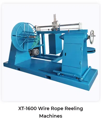
XT-1600 wire rope reeling machine, shown with reel assembly, traverse rail, drive motor, and tension control wheel
This configuration is broadly representative of equipment used for automatic wire spooling machine and automatic wire coiling machine duties across wire rope, cable, and rope manufacturing plants. Because the reel sits on an open frame rather than in an enclosed housing, maintenance staff have direct access to bearings, the drive chain or belt, and the traverse mechanism, which simplifies routine inspection. The layout also allows a forklift or overhead crane to approach the reel directly for loading and unloading finished coils, which is important in facilities that move large volumes of rope through the coiling station each shift.
Wire Rope Forming and Coiling Process
The coiling process on a typical wire rope making machine line follows a repeatable sequence from raw rope intake to finished, packaged coil. Understanding each step helps explain why consistent tension and guide alignment matter so much for final product quality.
- Wire rope arrives from the closing or stranding line and passes through straightening rollers that remove minor curvature.
- The rope enters the tension control unit, where braking force is set according to rope diameter and construction.
- The traverse guide positions the rope at the starting point on the empty reel and begins the first wrap.
- The reel motor and traverse motor operate together so each wrap sits next to the previous one without gaps or overlaps.
- When a layer is complete, the traverse direction reverses automatically and winding continues on the next layer.
- Once the target length or reel capacity is reached, the machine stops, the rope end is secured, and the finished coil is prepared for strapping and transport.
On semi automatic machines, an operator monitors this cycle and manually triggers the stop and rope cutting steps. On more advanced hydraulic wire rope forming machine and PLC controlled lines, sensors track rope length and layer count automatically, reducing the amount of manual attention needed during long production runs.
Production Capacity and Material Compatibility
Coiling and reeling equipment in this category is generally engineered around the diameter and weight of the wire rope being handled. Depending on model and configuration, machines are commonly grouped into light, medium, and heavy duty classes, which correspond to different reel sizes, motor power, and frame strength. The chart below presents a typical classification used across the industrial wire rope production line segment, based on common equipment specifications rather than any single certified test result.
This bar chart groups equipment into three general classes based on the maximum wire rope diameter each is typically built to accommodate. Light duty machines are commonly specified for diameters up to about twenty millimeters and are often used for smaller cable and rope products in general manufacturing. Medium duty machines extend that range to roughly thirty five millimeters and are frequently selected for standard construction and rigging rope. Heavy duty machines are built with reinforced frames and higher torque drives to handle diameters approaching fifty millimeters, which matches the requirements of large scale lifting, mining, and marine rope. The exact figure for any specific machine depends on its motor power, reel size, and frame design, so this chart should be read as a general reference rather than a fixed specification for every model. Material compatibility across these classes typically includes carbon steel wire, galvanized steel wire, various alloy steel wires, and stainless steel wire rope, since the coiling mechanism itself works primarily with rope diameter and stiffness rather than the specific steel grade.
| Equipment Class | Typical Diameter Range | Common Materials |
|---|---|---|
| Light Duty | Up to 20 mm | Carbon steel wire, stainless steel wire |
| Medium Duty | 20 to 35 mm | Galvanized steel wire, alloy steel wire |
| Heavy Duty | 35 to 50 mm | High tensile alloy wire, marine grade wire rope |
Automation Level and Control System
Modern automatic wire coiling machine systems are generally offered in semi automatic and full automatic configurations. In a semi automatic setup, the operator sets tension and starts the cycle, while the traverse and speed synchronization run automatically. In a full automatic setup, a programmable logic controller manages rope length counting, layer changes, tension feedback, and stop conditions, which reduces the level of operator attention required during continuous production. The radar chart below summarizes general performance characteristics associated with well engineered equipment in this category, presented on a simple relative scale for illustration rather than as results from a formal comparative test.
The radar chart plots six general characteristics that buyers commonly evaluate when reviewing coiling and reeling equipment, including automation level, control precision, structural durability, capacity flexibility, maintenance simplicity, and even layer winding quality. Automation level reflects how much of the winding cycle runs without manual input once the process starts. Control precision relates to how accurately the tension and traverse systems respond to changes in rope diameter or speed. Structural durability reflects frame and component design intended to withstand repeated heavy loading over time. Capacity flexibility indicates how well a single machine can handle a range of rope diameters and reel sizes rather than a single fixed product. Maintenance simplicity and even layer winding quality both relate to how easily the equipment can be inspected, adjusted, and kept in good working order during regular use. These six dimensions are presented together to give readers a general framework for evaluating equipment rather than to assign a precise numerical score to any single machine.
Application Industries for Wire Rope Coiling Equipment
Wire rope rolling and reeling machines are used wherever finished rope, cable, or similar flexible steel products need to be wound onto a reel for storage, transport, or direct use. Common application industries include construction, where rope is used in cranes, hoists, and scaffolding systems, mining, where rope handles heavy loads in shafts and haulage systems, marine and shipping, where mooring and rigging rope must be coiled without introducing twist, and general lifting and rigging operations across manufacturing plants. According to a market research report published by Persistence Market Research, construction represents the leading application segment for steel wire rope, contributing over thirty nine percent of market revenue in 2025, with the remaining share distributed across mining, marine, oil and gas, and other industrial and crane related uses.
The donut chart above summarizes this application distribution in visual form. The construction segment forms the largest single share, driven by ongoing demand for cranes, elevators, and material handling equipment on building and infrastructure sites. The combined remaining share reflects the broad range of other sectors that rely on properly coiled wire rope, including mining haulage and shaft systems, marine mooring and towing operations, oil and gas drilling and lifting, and general industrial crane use. Because these end use sectors have different duty cycles and environmental conditions, many plants operate more than one type of coiling and reeling machine to match rope diameter, coating, and packaging requirements for each market they serve. This distribution also explains why heavy duty rope rolling equipment supplier operations often maintain a range of reel sizes rather than a single fixed configuration, since customer requirements vary significantly between construction grade rope and specialized marine or mining rope.
Wire Rope Rolling vs Twisting Machine: What Is the Difference
A wire rope rolling or coiling machine and a wire rope twisting machine serve different stages of the manufacturing process, and understanding the distinction helps engineers and buyers select the correct equipment for a given production line. A twisting machine, sometimes called a stranding or closing machine, forms the wire rope itself by twisting individual wires into strands and then twisting those strands around a core. A rolling or coiling machine operates after the rope is already formed, and its role is to wind the finished rope onto a reel or drum for storage and shipment.
| Aspect | Rolling or Coiling Machine | Twisting or Closing Machine |
|---|---|---|
| Primary Function | Winds finished rope onto a reel | Forms rope by twisting wires and strands |
| Position in Line | Downstream, near final packaging | Upstream, during rope formation |
| Key Mechanism | Traverse guide and tension control | Rotating cage or bow for twisting |
| Typical Output | Evenly wound reel of finished rope | Continuous length of formed wire rope |
In an integrated wire rope manufacturing line, these two machine types are typically connected by intermediate processes such as galvanizing, lubrication, or inspection, so the twisted rope travels from the closing machine through these stations before reaching the final coiling and reeling stage. Selecting the correct rolling or coiling machine for the end of the line depends primarily on the diameter range, weight, and packaging format needed for the finished rope, rather than on the twisting method used earlier in the process.
Industry Growth Outlook for Wire Rope and Related Equipment
Demand for wire rope handling equipment, including coiling and reeling machines, tends to track overall growth in the wire rope market itself, since every meter of rope produced eventually needs to be wound and packaged. According to a report from MarketsandMarkets, the global steel wire rope market is projected to grow from about ten point five billion United States dollars in 2025 to nearly thirteen point nine billion United States dollars by 2030, at a compound annual growth rate of approximately five point eight percent. The chart below presents an illustrative growth trajectory calculated from this reported rate, showing how a market of this size might progress year by year if growth remains steady across the period.
This area chart shows a steady upward line from just above ten billion dollars in 2025 toward nearly fourteen billion dollars in 2030, consistent with the compound annual growth rate reported by MarketsandMarkets for the global steel wire rope market. The gradual slope reflects a mature industry with consistent, rather than explosive, expansion, which is typical for capital equipment and infrastructure related markets. Growth of this kind is generally attributed to continued investment in construction, infrastructure, and mining projects around the world, along with steady replacement demand as existing rope reaches the end of its service life. As overall rope production expands, coiling and reeling capacity at the end of manufacturing lines needs to expand alongside it, which supports ongoing investment in automatic wire spooling machine and related handling equipment. Readers should treat the chart as an illustrative trend derived from a single published growth rate rather than an exact year by year forecast, since actual market figures can vary by region and by reporting methodology.
Maintenance Guidance and Equipment Lifespan
Routine maintenance plays a significant role in keeping a wire rope rolling machine running smoothly over its service life. A basic maintenance schedule generally covers lubrication of bearings and drive components, inspection of guide rollers for wear or misalignment, and periodic checks of the tension control mechanism to confirm it still responds accurately across the rope diameter range the machine is expected to handle.
- Check and lubricate reel shaft bearings and gearbox oil levels according to the manufacturer schedule.
- Inspect traverse guide rollers and rails for wear, since uneven surfaces can cause inconsistent layer winding.
- Verify tension control settings periodically, particularly after switching to a different rope diameter or material.
- Examine electrical control cabinets and wiring connections to reduce the risk of unplanned downtime.
- Keep the base frame and surrounding work area clear of debris that could interfere with reel tilting or rotation.
Facilities that follow a consistent maintenance routine generally experience fewer unplanned interruptions and can extend the practical service life of their wire rope making machine equipment. Because coiling machines operate continuously during production shifts, even small misalignments in the traverse system can accumulate into visible winding defects over time, which makes routine inspection an important part of overall equipment management rather than an optional task.
About Jiangsu Xingtai Hydraulic Manufacturing Co Ltd
Jiangsu Xingtai Hydraulic Manufacturing Co Ltd was founded in 1992 and is located in Taizhou City, Jiangsu Province, China. The company specializes in manufacturing hydraulic wire rope pressing machines, wire rope annealing and tapering machines, aluminum sleeves, lifting clamps, and related wire rope handling equipment such as the coiling and reeling machines described in this article. Xingtai Hydraulic operates with production facilities, technical staff, testing equipment, and a quality management system aimed at consistent output across its equipment range.
The swaging components used in Xingtai Hydraulic machines are forged from high strength alloy steel, and the machine body for its pressing equipment is manufactured from a single block of material to support structural integrity and long service life. The company's hydraulic systems use a dual pressure pump oil supply arrangement, which is designed to allow fast upward and downward movement while maintaining a controlled pressing process, contributing to pressing quality and production efficiency on its hydraulic product lines.
Xingtai Hydraulic equipment has been shipped to customers in a number of countries, including the United Kingdom, Australia, the Netherlands, Latvia, Malaysia, Thailand, India, Russia, Botswana, and Poland, among others. The company works from a philosophy centered on consistent quality, competitive positioning, and long term commitment to customer relationships, and continues to serve both existing and new clients across its range of wire rope processing and handling equipment, including wire rope machine supplier relationships built over years of export experience.
Frequently Asked Questions
Q1: What is the main purpose of a wire rope rolling machine
A1: Its main purpose is to wind finished wire rope evenly onto a reel or drum, using coordinated reel rotation, traverse guiding, and tension control to prevent tangling or uneven layers.
Q2: How is a wire rope rolling machine different from a twisting machine
A2: A rolling or coiling machine winds already formed rope onto a reel, while a twisting or closing machine forms the rope itself by twisting wires and strands together earlier in the production line.
Q3: What wire rope diameters can this type of equipment typically handle
A3: Depending on model and configuration, machines in this category are commonly built for diameters ranging from about ten to fifty millimeters, covering light, medium, and heavy duty applications.
Q4: What materials are compatible with wire rope coiling machines
A4: These machines commonly handle carbon steel wire, galvanized steel wire, various alloy steel wires, and stainless steel wire rope, since the coiling mechanism responds mainly to diameter and stiffness.
Q5: What maintenance does a wire rope reeling machine require
A5: Routine maintenance generally includes bearing and gearbox lubrication, inspection of guide rollers and rails, periodic tension control checks, and regular review of electrical control components.


")
")

If you require custom hydraulic equipment or technical consultation, please feel free to contact the Xingtai Sales and Engineering Team.
-
 +86-523-86934677
+86-15896002505 -
 [email protected]
-
 +86-15896002505
-
 No. 3 Longgang Road, Gaogang Port Street, Taizhou City, China.
Copyright © Jiangsu Xingtai Hydraulic Manufacturing Co., Ltd. All Rights Reserved. Custom hydraulic machinery manufacturers Wholesale wire rope swagers Factory

