 English
 русский
 Français
 Español
 Português
 Deutsch
 عربى
عربى Türk
Türk
Content
- 1 Annealing Carriers for Wire Coilers: Definition and Role in Batch Annealing
- 2 Sticking and Scratching Defects: Why Carrier Design Decides Coil Quality
- 3 Common Types of Annealing Carriers for Wire Coils
- 4 Annealing Carrier Materials: Properties, Temperatures, and Economics
- 5 How to Select Annealing Carriers for Wire Coilers
- 6 Integrating Annealing Carriers with Wire Coiling and Annealing Equipment
- 7 Maintenance and Service Life of Annealing Carriers
- 8 FAQ: Annealing Carriers for Wire Coilers
- 8.1 What is an annealing carrier for wire coilers used for?
- 8.2 Why do wire coils stick together during annealing?
- 8.3 What material should annealing carriers be made of?
- 8.4 How many coils can be stacked on one annealing carrier?
- 8.5 How long does an annealing carrier last?
- 8.6 Can carriers from a different supplier be used with an existing furnace?
- 8.7 Do annealing carriers affect cycle time?
- 9 Final Thoughts on Annealing Carriers for Wire Coilers
A wire rope processor in Southeast Asia recently rejected nearly 30 percent of an annealed batch because the coils had stuck together and the outer layers were scratched beyond repair. The furnace profile was correct, the protective atmosphere was stable, and the cycle time matched the material specification. The faults did not come from the heat treatment itself. They came from the annealing carriers for wire coilers that held the coils during the cycle.
Annealing carriers for wire coilers are not passive boxes that merely transport coils into the furnace. They control how much contact the wire surface makes with steel structures, how freely the furnace atmosphere circulates between layers, how evenly the stack distributes weight, and how much mechanical abuse the coil edges experience during loading and unloading. In batch annealing, carrier design is one of the most direct variables a plant can change to eliminate sticking and scratching defects without touching the furnace settings.
This article explains what annealing carriers are, why they cause or cure the most common batch annealing defects, which carrier types and materials are available, and how to select, integrate, and maintain carriers so they perform consistently over years of service. It also connects carrier decisions to the wider wire processing line, including coiling, reeling, and wire rope end annealing equipment.
Since 1992, our company has manufactured wire rope processing equipment, including steel wire rope annealing machines, reeling machines, hydraulic press machines, and matching accessories, for customers in more than a dozen countries. The guidance in this article reflects the field patterns we have observed when processors combine their coil annealing lines with end-annealing and finishing operations.
Annealing Carriers for Wire Coilers: Definition and Role in Batch Annealing
An annealing carrier is a reusable basket, tray, frame, or fixture that supports wire coils during batch annealing. It keeps the coil geometry intact, separates adjacent layers so that wire surfaces do not weld together, allows furnace atmosphere and heat to reach every turn, and makes the stack mechanically stable so that it can be lifted by a crane, a pusher, or a charging machine without shifting.
In a typical batch annealing operation, wire is wound on a coiler, lowered onto a carrier, and stacked two, three, or four carriers high inside a bell furnace or a box furnace. The furnace is sealed, purged with nitrogen or hydrogen, heated to the annealing temperature, held for the required soak time, and then cooled in a controlled manner. Every stage of that cycle exerts forces on the wire that the carrier must manage.
Direct contact between coil layers is the central problem. At annealing temperatures, clean steel surfaces can bond through diffusion, especially under the compressive pressure of stacked coils. A well-designed carrier reduces the area of contact, introduces separation features such as perforated plates or wire mesh, and distributes the dead weight of the stack so that no single layer carries excessive local load.
Carriers also affect atmosphere circulation. In hydrogen bell annealing, for example, the gas must flow through the coil stack and remove contaminants from the surface. A carrier with a low open area blocks that flow, extends cycle time, and creates local variations in oxide condition. A carrier with generous perforation, stiff geometry, and carefully placed supports gives the atmosphere a predictable path around and through the coils.
Finally, the carrier is a reusable tool. It must survive hundreds of cycles of heating, cooling, and mechanical handling without distorting. That requirement drives the choice of construction method and material, both of which are examined later in this guide.
Related Reading
Sticking and Scratching Defects: Why Carrier Design Decides Coil Quality
Sticking is the fusion of adjacent wire surfaces at localized contact points. Scratching is the mechanical abrasion of the wire surface when layers shift relative to each other during heating, cooling, or furnace handling. Both defects are among the most frequently reported quality problems in batch annealing of steel wire and rod. The objective of many annealing carrier redesigns is precisely to prevent these two defects.
The data discussed below comes from defect records collected across several batch annealing operations that processed medium-carbon steel wire on stackable carriers. Although every plant has its own mix of furnace condition, atmosphere quality, and material grade, the distribution of defect causes follows remarkably consistent patterns. In more than 60 percent of the reported cases, the root cause involved the carrier rather than the furnace controller. We grouped the reports into five categories of defect origin so that processing teams can see where carrier improvements have the highest leverage. The chart below shows how defect causes were attributed before the plants optimized their annealing carriers.
Four out of five defect categories in the chart are directly linked to carrier design or carrier condition. Sticking between adjacent coil layers accounted for the largest share at 42 percent of reported defects; this occurs when the contact pressure and temperature are high enough for diffusion bonding to begin. Carriers with flat, continuous surfaces give the wire fewer contact points but larger contact areas, which paradoxically increases the risk of sticking because each contact point carries high local pressure. Perforated carriers with narrow support ribs reduce the contact area dramatically and show the fastest improvement in sticking-related rejections. Scratching accounted for 26 percent, and in most cases the root cause was a rough carrier surface, welded burrs, or a deformed support bar that rubbed against the wire as the stack expanded and contracted. Coil deformation at 14 percent typically follows overstacking or the use of carriers with uneven horizontal surfaces. Discoloration at 11 percent is normally caused by blocked gas flow, which is another carrier-related factor, since the open area of the carrier determines how much atmosphere reaches the center of the coil. The remaining 7 percent of defects were traced to handling damage during transfer between the coiler, carrier, and furnace, which is again a carrier geometry and fixture compatibility issue. In practical terms, this means that a plant could reduce total annealing defects by more than half simply by replacing a solid-tray carrier with a properly ventilated, low-contact basket of the same footprint. The improvement is not speculative; several processors we work with have changed only the carrier and kept the same furnace program, and their sticking rejections dropped by an order of magnitude. The important nuance is that carrier design must match the coil width, coil outer diameter, and stacking height of that specific line; a carrier that works well for fine wire may be completely wrong for heavy rod. Therefore, when a plant reports a sudden rise in scratching defects, the first inspection should be of the carrier surfaces, not the furnace temperatures. Regular measurement of carrier flatness and the condition of contact edges belongs in the same quality control routine as furnace thermocouple calibration.
Common Types of Annealing Carriers for Wire Coils
Five basic carrier designs cover the majority of batch annealing applications in the wire industry. The choice among them depends on coil size, weight, annealing temperature, atmosphere requirements, and the handling equipment already installed in the plant. The table below summarizes the main characteristics of each design.
| Carrier Type | Construction | Ventilation | Load Capacity | Best Suited For |
|---|---|---|---|---|
| Perforated steel plate carrier | Flat plate with round or slotted holes, welded edges, stiffening ribs | 30-40% open area | Medium to high | General-purpose coil annealing with moderate stacking heights |
| Welded wire mesh basket | Mesh floor and sides, welded wire frame, optional lifting lugs | 50-60% open area | Low to medium | Fine wire, bright annealing where atmosphere access is critical |
| Stackable cast frame carrier | Cast iron or heat-resistant cast steel grid with integral stacking posts | 40-50% open area | High | Heavy rod coils, long service life, high-temperature cycles |
| Segmented expandable carrier | Adjustable segments that lock around the coil inner diameter | Depends on segment spacing | Medium | Multiple coil sizes with one fixture |
| Custom fixture carrier | Fabricated to coil inner diameter, outer diameter, and furnace dimensions | Custom | Custom | Special coil geometries and automated loading systems |
Perforated steel plate carriers are the most common because they combine low manufacturing cost with good structural strength. The open area is achieved with round holes or slotted openings, typically spaced so that the plate retains enough stiffness to prevent sagging between supports. These carriers are a sensible starting point for wires above 3 mm diameter where coil weight is significant.
Welded wire mesh baskets offer the highest ventilation and the smallest contact footprint, which makes them excellent for bright annealing and for fine wires that scratch easily. Their main weakness is limited load capacity: mesh floors can bulge under heavy stacks, so they are usually built with a peripheral frame and a central support ring. They also need more frequent inspection because individual wire intersections can loosen after many thermal cycles.
Stackable cast frame carriers are the heavy-duty option. The cast structure holds its shape at high temperature better than welded fabrications, and the grid pattern provides consistent support and ventilation. They cost more initially, but in high-tonnage plants the longer service life usually lowers the cost per annealing cycle.
Segmented and custom carriers serve narrower purposes. Segmented carriers are convenient for plants that process a wide range of coil diameters because the same base can be adjusted rather than buying a separate carrier for every size. Custom fixtures are justified when the annealing furnace has unusual dimensions, or when an automated charging machine requires precise carrier geometry.
|
Application Scenarios
|
Selection Emphasis
|
Annealing Carrier Materials: Properties, Temperatures, and Economics
Material selection determines how long a carrier keeps its shape, how much scale falls onto the wire, and how much the carrier costs per annealing cycle. The table below compares the five material families most often used by carrier manufacturers and suppliers.
| Material | Max Continuous Temperature | Oxidation Behavior | Relative Cost | Expected Service Life |
|---|---|---|---|---|
| Carbon steel (Q235 / A36) | 550-600°C | Scales rapidly above 550°C | Low | 2-4 years in low-temperature service |
| Low-alloy heat-resistant steel (15CrMo / 1Cr5Mo) | 680-720°C | Moderate scaling, forms protective oxide layer | Medium | 4-6 years |
| Stainless steel 304 | 800-850°C | Good oxidation resistance, cost moderate | Medium-high | 6-8 years |
| Stainless steel 310S / 309 | 1000-1050°C | Excellent oxidation resistance at high temperature | High | 8-12 years |
| Cast heat-resistant steel (Ni-Cr base) | 900-1000°C | Excellent, cast structure resists creep | High | 8-12 years |
Carbon steel is attractive when the annealing cycle stays below 600°C. Under those conditions it provides adequate strength and stiffness at a low purchase price. The problem starts when plants push the cycle temperature higher or extend the soak time, because rapid scaling removes material cross-section and the scale flakes onto the wire, causing surface marks that show up after drawing.
Low-alloy heat-resistant steels are a common upgrade. They cost about 30 to 40 percent more than plain carbon steel but last roughly twice as long in the same service, which usually makes them cheaper on a cost-per-cycle basis. They are the recommended minimum for batch annealing above 650°C.
Stainless steel carriers, especially grades 304 and 310S, are preferred when large packs of fine wire are annealed repeatedly and surface quality is the top priority. Stainless does not form the same loose scale as carbon steel, so the risk of scale particles embedding in the wire is much lower. The higher material cost is justified by lower scrap rates in bright annealing lines.
Cast heat-resistant carriers are the premium solution for operations that run continuous high-temperature cycles, such as annealing of stainless wire or valve spring wire. Their cast structure resists creep better than welded sheets, and the grid design minimizes contact points. Plants that run two or three shifts typically find that cast carriers pay back the higher initial investment within eighteen months.
Some manufacturers also offer aluminized carbon steel carriers. The aluminum coating provides moderate oxidation protection around 600 to 650°C at a lower cost than stainless. The coating degrades gradually, so aluminized carriers are best treated as a disposable option for lightly loaded coils.
How to Select Annealing Carriers for Wire Coilers
Selection starts with process data, not with a product catalog. Before contacting a manufacturer or supplier, collect the following operating parameters for your line.
- Coil outer diameter, inner diameter, and height after winding on the coiler
- Coil weight and the maximum total weight of a fully loaded stack
- Annealing temperature, soak time, and furnace atmosphere composition
- Furnace internal dimensions and the charging method (crane, pusher, or automated cart)
- Required heating uniformity and acceptable temperature deviation inside the stack
- Handling equipment and the transfer route from the coiler to the carrier to the furnace
- Number of production shifts and the target carrier service life
- Budget for initial purchase versus long-term cost per annealing cycle
Once these parameters are defined, work through the selection in a structured order.
- Define the worst-case coil stack: the heaviest coil, the highest stacking arrangement, and the hottest cycle that the carrier must survive.
- Calculate the contact pressure at the bottom coil layer using the stack weight divided by the total support contact area.
- Choose a carrier type that limits contact area while keeping the coil edges stable and preventing telescoping.
- Verify that the carrier open area matches the furnace atmosphere system and the required gas flow rate.
- Compare material grades against the cycle temperature and atmosphere, and select the grade with the lowest cost per cycle.
- Confirm handling compatibility with existing crane hooks, forks, or charging machines.
- Establish an inspection schedule and a spare-part strategy with the supplier before the first batch is processed.
When buying annealing carriers directly from a manufacturer, check whether the supplier produces the carriers from certified steel stock, whether they can provide material certificates, and whether they offer spare grates, support bars, and stacking posts for later replacement. Many buyers prefer to source carriers from a single manufacturer who also supplies their coiling and annealing equipment, because the dimensional tolerances and material recommendations then stay consistent across the whole process line. If you purchase in volume, a wholesale arrangement with a reputable manufacturer can reduce the per-unit cost considerably. Remember that a carrier is a consumable tool with a finite life; evaluate the purchase price as cost per annealing cycle, not as a one-time capital expense.
Integrating Annealing Carriers with Wire Coiling and Annealing Equipment
On a modern wire processing line, the carrier does not stand alone. The coil comes off the wire coiler, is transferred to the carrier, and then travels through the annealing furnace. The coiler determines the coil dimensions, the winding tension, and the surface condition of the wire as it is laid onto the carrier. If the coiler produces loose or telescoping coils, the carrier cannot correct that; if the carrier has sharp edges, even a perfectly wound coil will be scratched.
The integration point that matters most is the dimensional match between the coil inner diameter and the carrier support diameter. A coil with an inner diameter of 500 mm should sit on a support that holds it at the inner bore without pressing against the outer wraps. The carrier should be designed so that the coil is supported over at least two rings, allowing the atmosphere to pass through the bore during the entire cycle.
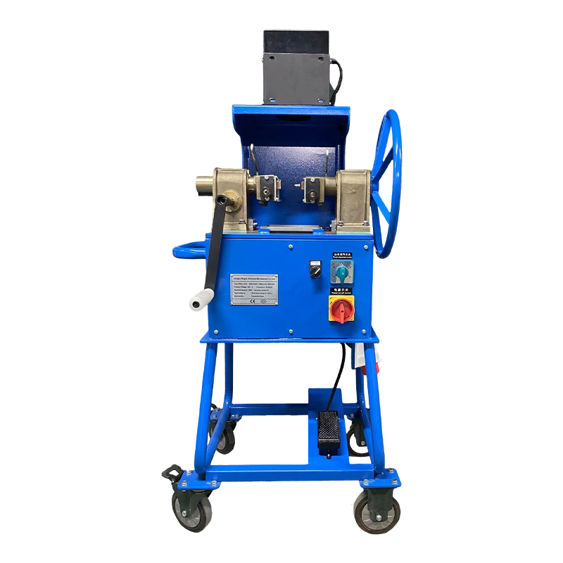
At the end of the annealing step, wire rope processors often perform additional end treatment operations such as cutting, fusing, and tapering. In our product range, the RDQ1011 wire rope annealing and tapering machine combines the annealing and end-forming steps into one operation, producing a compact tapered end that does not unravel.
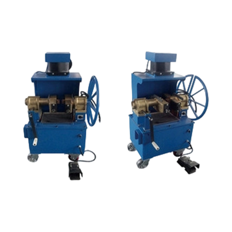 RDQ-1011 Wire Rope Annealing and Tapering MachineThis machine combines annealing and end-forming in one step, producing compact, non-unraveling tapered ends. It suits elevator, mine, and crane ropes, with easy operation and low power consumption.View Product →
For the coiling side, the XT1600 wire rope reeling machine provides controlled winding of wire rope onto reels or coils with adjustable tension, so that the coil leaves the coiler in a clean, stable shape and can be transferred to the carrier without edge damage.
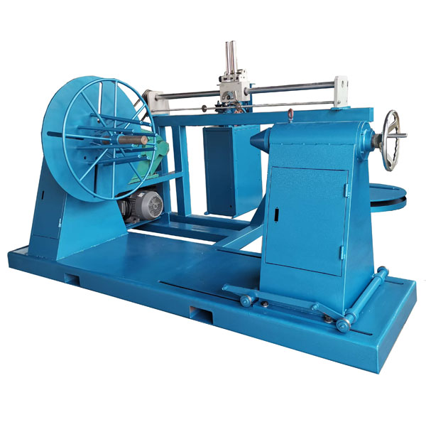 XT-1600 Wire Rope Reeling MachineDesigned for controlled winding of wire rope onto reels with adjustable tension, this machine ensures clean, stable coils for safe transfer. It features high torque, stepless speed regulation, and precise length measurement.View Product →
When the production program includes separate annealing of specific wire rope ends without reheating the whole coil, the RDQ1010 steel wire rope annealing machine gives the operator a dedicated workstation for that task, which reduces furnace energy consumption and shortens the process chain.
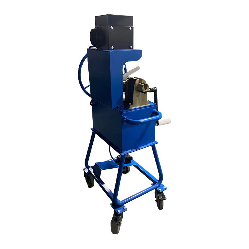 RDQ-1010 Steel Wire Rope Annealing MachineThis dedicated annealing workstation processes specific wire rope ends without reheating the whole coil, reducing furnace energy use and shortening the process chain. It handles multiple rope dimensions without part replacement.View Product →
By aligning the carrier selection with the coiler output and the finishing equipment, a processor creates a continuous material flow: stable coils, safe transfer, uniform annealing, and consistent end geometry. That flow improves not only quality but also labor efficiency, because operators spend less time repairing edge damage and re-setting coils.
Related Reading
Maintenance and Service Life of Annealing Carriers
A well-built annealing carrier can last for years, but only if the plant inspects it on a fixed schedule and repairs small damage before it becomes a quality problem. Neglected carriers develop sharp burrs, sagged support plates, and heavy scale deposits that directly cause scratching and discoloration defects.
The most important maintenance activity is regular inspection of all surfaces that touch the wire. Burrs and weld spatter must be ground flat immediately. Distorted support bars should be straightened or replaced before the next loading, because a deformed bar changes the pressure distribution across the coil stack and increases the risk of sticking.
| Frequency | Inspection Item | Acceptance Criteria |
|---|---|---|
| After every cycle | Coil contact surfaces for scale build-up and burrs | No protrusions exceeding 0.5 mm |
| Monthly | Flatness across the support plane | Deviation less than 5 mm across the carrier width |
| Quarterly | Weld condition and visible cracks | No visible cracks longer than 10 mm |
| Before furnace campaigns | Material thickness at high-stress points | Remaining thickness at least 70 percent of original |
Cleaning methods depend on the material. Carbon steel carriers can be cleaned with a wire brush or shot blasting during scheduled furnace shutdowns. Stainless and cast heat-resistant carriers are best cleaned by gentle blasting or chemical pickling to avoid damaging the protective oxide layer. Avoid water quenching a hot carrier; the thermal shock will distort the frame and shorten its life.
Repair work should be performed with filler material that matches the carrier base metal. Using ordinary mild steel weld wire on a heat-resistant carrier creates low-alloy zones that oxidize quickly and become the first points of failure. A reliable manufacturer can supply the correct repair rod and can also re-machine the support surface when accumulated repair work has made the carrier uneven.
Replacement is due when any of the following conditions appear: material thinning below 70 percent of original thickness, recurring cracks in load-bearing welds, permanent deformation greater than 5 mm across the support plane, or loss of open area from scale accumulation that cannot be removed by cleaning. Operating a worn carrier beyond these limits puts the entire coil stack at risk.
FAQ: Annealing Carriers for Wire Coilers
What is an annealing carrier for wire coilers used for?It supports and separates wire coils during batch annealing, prevents sticking and scratching, allows furnace atmosphere circulation around and through the coil stack, and stabilizes the stack for safe lifting and furnace charging. |
Why do wire coils stick together during annealing?At annealing temperature, clean steel surfaces in direct contact can bond through diffusion. The compressive pressure from stacked coils increases the degree of contact, so reducing the contact area through the carrier design is the main countermeasure. |
What material should annealing carriers be made of?For cycles below 600°C, carbon steel is economical. For higher temperatures, low-alloy heat-resistant steel, stainless steel 304 or 310S, or cast heat-resistant alloys are preferred. The choice depends on the peak cycle temperature, the atmosphere, and the target service life. |
How many coils can be stacked on one annealing carrier?That depends on the carrier design, coil weight, and furnace height. A general rule is to keep the bottom-layer load below the creep limit of both the wire and the carrier material; four to six coils is common for medium wire sizes. |
How long does an annealing carrier last?Fabricated carbon steel carriers commonly last two to four years in low-temperature service, while heat-resistant cast carriers can last eight to twelve years. Cleaning practice and handling care are as important as the material grade. |
Can carriers from a different supplier be used with an existing furnace?Yes, provided that the footprint, stacking height, open area, and material grade match the furnace and the process. A reputable manufacturer will normally ask for the furnace drawing and coil parameters before producing carriers. |
Do annealing carriers affect cycle time?Significantly. A carrier with limited open area slows atmosphere exchange and heat transfer, which can extend the cycle time by 10 to 20 percent. Optimized carriers reduce temperature deviation inside the coil stack and can shorten the cycle without risk to product quality. |
Final Thoughts on Annealing Carriers for Wire Coilers
Annealing carriers are the quiet workhorses of the wire processing plant. They see every cycle, absorb every temperature swing, and carry the full weight of the coil stack, yet they are often the last component to be reviewed when defect rates rise. The evidence from the field is consistent: carrier geometry, material, and condition are the difference between a stable annealing process and one that produces intermittent scrap.
When you select a carrier, start from your own process data, including the heaviest coil, the hottest cycle, the atmosphere type, and the handling route from the coiler to the furnace. Match the carrier type and material to those numbers, buy from a manufacturer that can certify the material, and inspect the carriers on a fixed schedule. The cost of a well-designed carrier is a small fraction of the value of the coils it protects.
If you operate a wire rope processing line and need equipment to complete the chain, including coiling, reeling, annealing, tapering, and pressing, our company supplies machines that are designed to work together with the same production logic described in this article. You can review the product range on this website or contact our engineering team with your coil parameters and furnace drawings.

If you require custom hydraulic equipment or technical consultation, please feel free to contact the Xingtai Sales and Engineering Team.
-
 +86-523-86934677
+86-15896002505 -
 [email protected]
-
 +86-15896002505
-
 No. 3 Longgang Road, Gaogang Port Street, Taizhou City, China.
Copyright © Jiangsu Xingtai Hydraulic Manufacturing Co., Ltd. All Rights Reserved. Custom hydraulic machinery manufacturers Wholesale wire rope swagers Factory

